Ech0 - 22 / 08 / 2020

Inter-VLAN Routing

Previously we learned about VLANs and how they separate computer subnets. We also learned about routing in general, so that chapter is about combining the two. We create VLANs to separate computer networks, but how do we route traffic in between the two ?

Initial Setup

Link the gigabit ports in between router and switch and separate the PC connections to the switch with the previous VLAN configuration: vlan 10 (1-10 LEFT) vlan 20 (11-20 RIGHT)

Nothing new here, we saw this in the previous chapter, we setup the VLANs in the switch CLI:


Switch>en
Switch#conf t

Switch(config)#vlan 10
Switch(config-vlan)#name LEFT
Switch(config-vlan)#exit

Switch(config)#vlan 20
Switch(config-vlan)#name RIGHT
Switch(config-vlan)#exit

Switch(config)#int range fa0/1-10
Switch(config-if-range)#switchport mode access
Switch(config-if-range)#switchport access vlan 10
Switch(config-if-range)#exit

Switch(config)#int range fa0/11-20
Switch(config-if-range)#switchport mode access
Switch(config-if-range)#switchport access vlan 20
Switch(config-if-range)#exit

Switch(config)#exit
Switch#copy run start
Switch#show vlan

And we see the active Vlan Configuration:

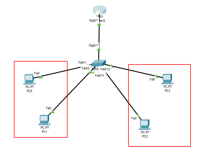
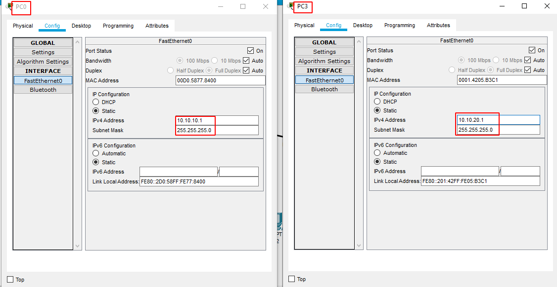
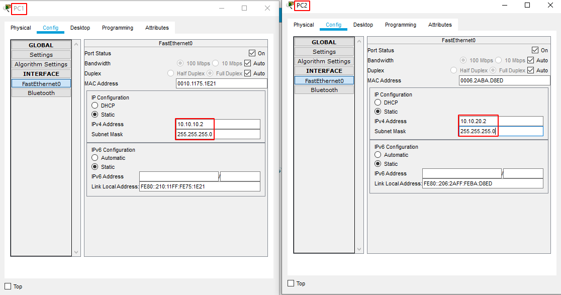
Router Configuration


Now the idea here is to have 1 virtual gateway per set of computers, so we will have 2 networks for only ONE router interface Because of this we will need to enable trunk mode on the switch's connection to the router.


Switch#conf t
Switch(config)#int gig0/1
Switch(config-if)#switchport mode trunk
Switch(config-if)#no shutdown
Switch(config-if)#exit
Switch(config)#exit
Switch#copy run start
Switch#exit
Switch>

Once that's done we configure the virtual interfaces in the router CLI:


Router>en
Router#conf t
Router(config)#int gig0/1.10
Router(config-subif)#encapsulation dot1Q 10
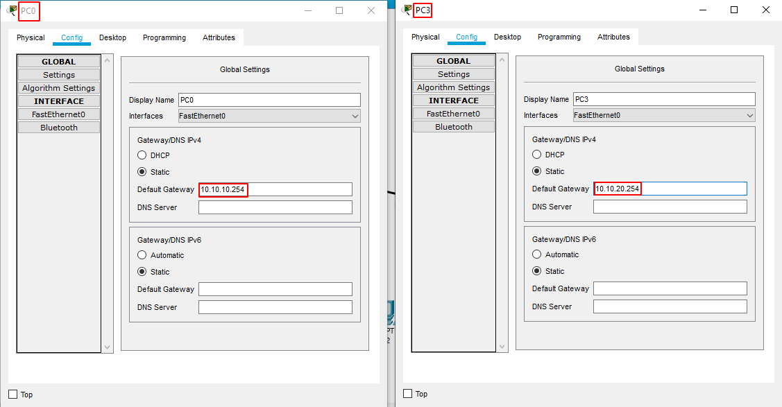
Router(config-subif)#ip address 10.10.10.254 255.255.255.0
Router(config-subif)#no shut
Router(config-subif)#ex

Here we configured the interface (gateway) for the LEFT VLAN (10), now we configure the RIGHT VLAN (20):


Router>en
Router#conf t
Router(config)#int gig0/1.20
Router(config-subif)#encapsulation dot1Q 20
Router(config-subif)#ip address 10.10.20.254 255.255.255.0
Router(config-subif)#no shut
Router(config-subif)#ex

Now that we configured both virtual interfaces (gig0/1.10 and gig0/1.20), we activate the PHYSICAL interface (gig0/1)


Router(config)#int gig0/1
Router(config-if)#no shut
Router(config-if)#ex
Router(config)#ex
Router#copy run start
Router#ex
Router>

And we have this result:

Testing Connectivity


All that's left to do is to configure the PC's gateways, static ip addresses and test if they can communicate with each other:


Now that's done, we can verify if the PCs can communicate with each other despite being in separate VLANs (in the previous chapter we saw that they couldn't)

And they can! We have verified that we were able to have multiple (virtual) router gateways linked to a single switch which also supported VLANs thanks to the dot1Q encapsulation.

You can download the pkt file here.

Next Chapter: DHCP Servers

My Bunker

Some Address 67120,
Duttlenheim, France.

About Ech0

This cute theme was created to showcase your work in a simple way. Use it wisely.