Ech0 - 03 / 10 / 2020

Advanced Inter-VLAN Routing

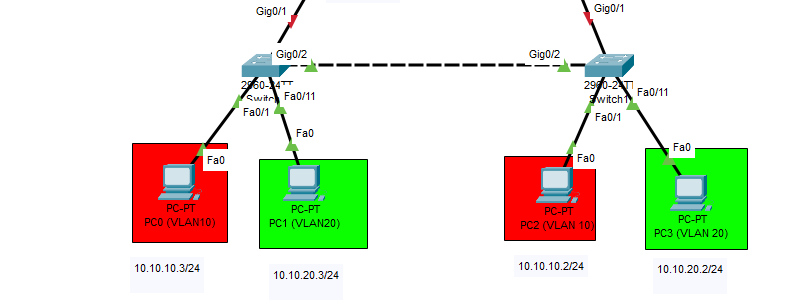
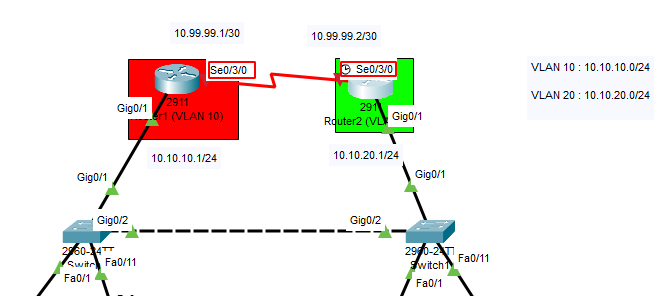
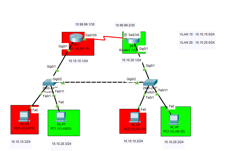
This is an exercise for us students to make sure we know how to do everything we mentionned in the previous chapters up until now, so we start from this network here:

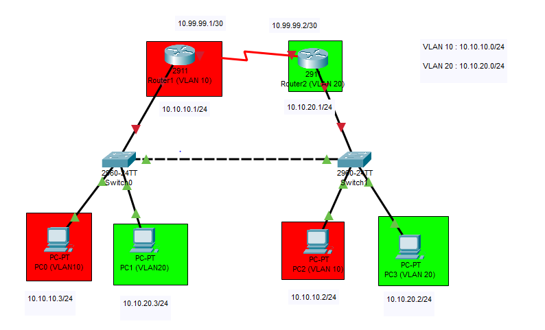
Not much has been done besides:

  1. placing PCs, Switches, and Routers
  2. Linking PCs to Switches (Fa0/1 and Fa0/11) for both switches switch
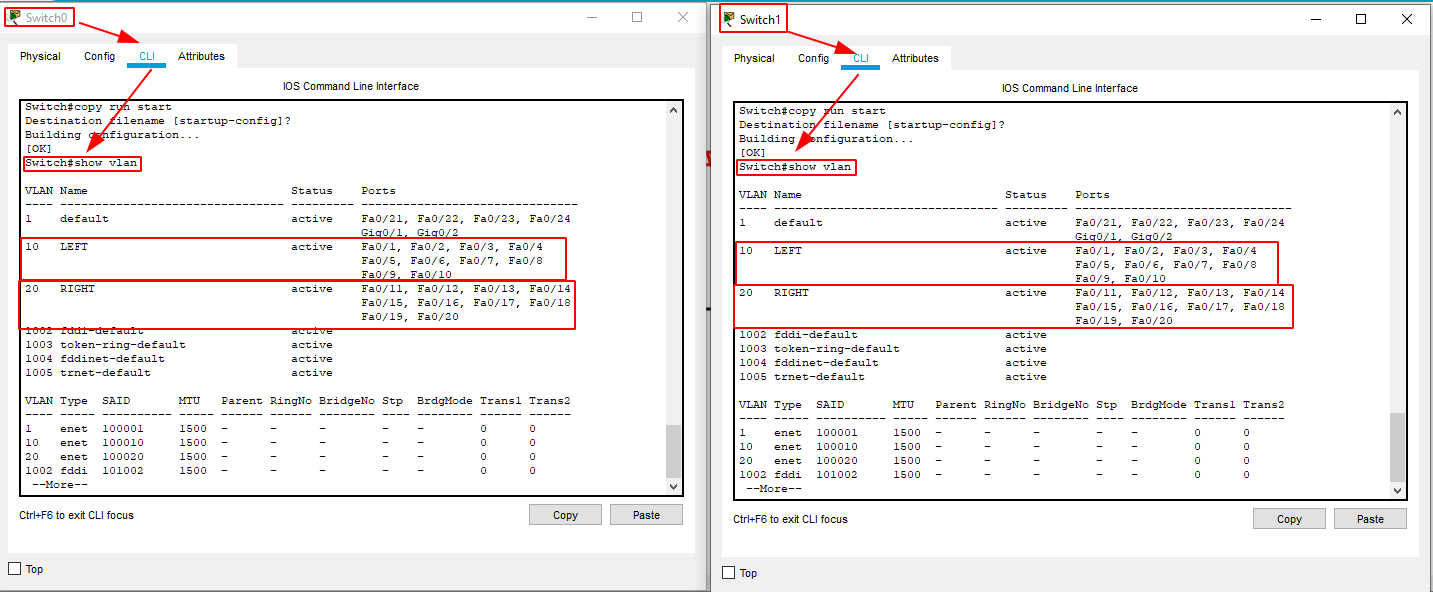
  3. We want VLAN 10 to be fa0/1-10 on both switches
  4. We want VLAN 20 to be fa0/11-20 on both switches
  5. Switches linked to each other on gig0/2 with copper pass through (for mode trunk)
  6. Switches linked to routers on gig0/1 <-> gig0/1 maybe mode trunk too
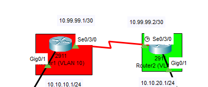
  7. Routers with HWIC-2T for serial connection (OFF > place hwic-2T > ON)
  8. Routers linked together using Serial DTE connection (thanks to HWIC-2T)

So we need to:

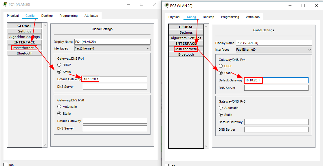
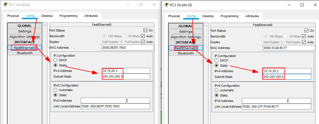
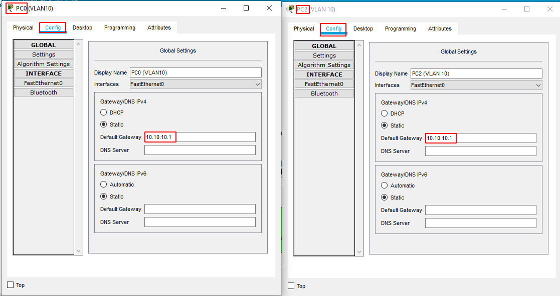
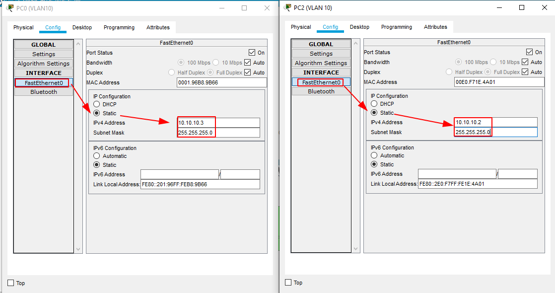
  1. give a static ip to each pc
  2. configure vlans on both switches
  3. enable switchport mode trunk in between the 2 switches
  4. enable switchport mode trunk in between switches and routers
  5. configure the vlan gateway on both routers (dot1Q)
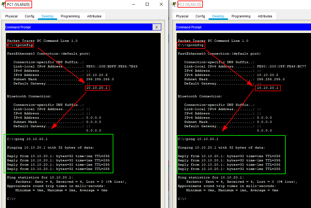
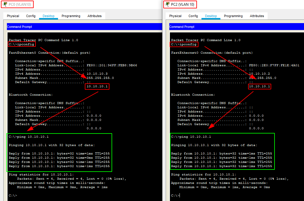
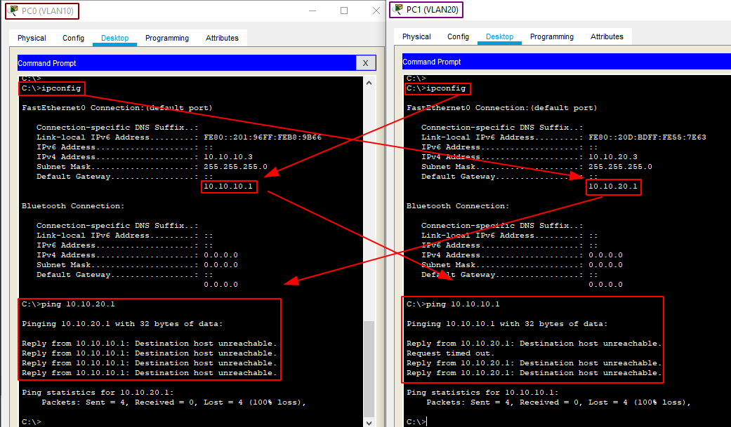
  6. Test connectivity within each vlan
  7. configure serial connection between routers
  8. configure static routing on both routers (to allow vlans to communicate with each other)
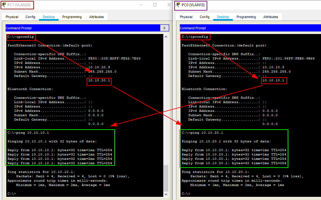
  9. Test connectivity between each vlans

Initial pkt file here.

Setting up the PCs and Switches

first we give a static ip to each PC as well as give them their default gateway

PC0 and PC2 (VLAN 10): PC1 and PC3 (VLAN 20):

Now that we took care of the PCs, we move onto the switches:

First we configure the VLANs on both switches:

left AND right switch:

>en
#conf t

config#vlan 10
config-vlan#name LEFT
config-vlan#ex
config#vlan 20
config-vlan#name RIGHT
config-vlan#ex

config#int range fa0/1-10
config if range#switchport mode access
config if range#switchport access vlan 10
config if range#ex

config#int range fa0/11-20
config if range#switchport mode access
config if range#switchport access vlan 20
config if range#ex
config#ex
#copy run start
#show vlan

Here we see that both VLANs are active on both switches:

Now packets that are coming from PCs are getting into the switches, where they will be given their proper VLAN tag, therefore the switchport mode trunk is needed in between the 2 switches on gig0/2 and between switches-routers on gig0/1:

left AND right switch:

Switch#conf t
Switch(config)#int range gig0/1-2
Switch(config-if-range)#switchport mode trunk
Switch(config-if-range)#no shutdown
Switch(config-if-range)#exit
Switch(config)#exit
Switch#copy run start
Switch#exit
Switch>

Routers configuration


First we configure the VLAN Gateways on both routers using dot1Q encapsulation (we also enable both the virtual AND the physical interfaces):

Router1 (VLAN 10)

>en
#conf t
config#int gig0/1.10
config-subif#encapsulation dot1Q 10
config-subif#ip address 10.10.10.1 255.255.255.0
config-subif#no shutdown
config-subif#ex
config#int gig0/1
config-if#no shutdown 
config-if#ex
config#ex
#copy run start
#ex
>


Router2 (VLAN 20)

>en
#conf t
config#int gig0/1.20
config-subif#encapsulation dot1Q 20
config-subif#ip address 10.10.20.1 255.255.255.0
config-subif#no shutdown
config-subif#ex
config#int gig0/1
config-if#no shutdown 
config-if#ex
config#ex
#copy run start
#ex
>


So we get this result:

Now we need to setup the serial connection in between the 2 routers on Se0/3/0 (10.99.99.1-2/30) (the /30 mask is 255.255.255.252) we only need 2 hosts there, so /30 is fitting:

Router1

>en
#conf t
config#int se0/3/0
config-if#ip address 10.99.99.1 255.255.255.252
config-if#no shut
config-if#ex
config#ex
#copy run start
#ex
>
Router2

>en
#conf t
config#int se0/3/0
config-if#clock rate 64000
config-if#ip address 10.99.99.2 255.255.255.252
config-if#no shut
config-if#ex
config#ex
#copy run start
#ex
>

And we get this result:

We test connectivity within both vlans:

and we see that both PCs in both VLANs are able to ping their own gateway, but we also see that they are not able to ping hosts from the other VLANs, proving that they are in fact separated:

You guessed it, now it's time to make sure both VLANs can communicate to each other thanks to static routing, hence this chapter's title.

Inter-VLAN Routing


The point here is to make sure the packets that come from VLAN 10 must be able to reach VLAN 20's gateway thanks to the serial connection in between the 2 routers, and the same thing with VLAN 20's packets must be able to reach VLAN 10's gateway. As we saw on Chapter 3 we can use static routing to do so:

Reminder: the static routing syntax is as follows:


#ip route <network-to-reach> <mask-of-network-to-reach> <next-hop>


Router1 (VLAN 10):

>en
#conf t
config#ip route 10.10.20.0 255.255.255.0 10.99.99.2
config#exit
#copy run start
#exit
>
Router2 (VLAN 20):

>en
#conf t
config#ip route 10.10.10.0 255.255.255.0 10.99.99.1
config#exit
#copy run start
#exit
>

Now that's done, we test the connection again:

And that's it ! we have been able to make the 2 VLANs communicate with each other thanks to static routing on both routers.

You can download the finished pkt file here.

Next chapter ???

My Bunker

Some Address 67120,
Duttlenheim, France.

About Ech0

This cute theme was created to showcase your work in a simple way. Use it wisely.